Map Drawing
- Getting started
Training
Modelling is the functional heart de Forge. It is in this phase that the user builds the environment in 3D, adding and arranging structures, areas, and other elements to faithfully represent a building, site, or outdoor space.
This chapter covers the Geometric creation tools, the methods of Manual or assisted plotting, the Vertex Management, as well as the Options for editing existing shapes. It also includes advanced functions such as precise alignment, the creation of openings, or constrained drawing according to geometric rules (right angles, parallels).
The objective is to provide the user with the means to produce a Accurate and usable spatial representation, while facilitating corrections, adjustments and enrichments over time.
Prerequisites
- Have Forge installed
- Have launched Forge connected to the target organization where the card will be stored.
- Have knowledge of the Forge interface and the role of its different parts.
- Have created and posted a map.
Structures
Structures are used to represent rooms and walls.
Drawing a structure
To draw a structure, you have to click on this tool:
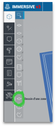
Then, by successive left clicks in the map, draw the contours. Once the shape is made, press right click to validate the path.
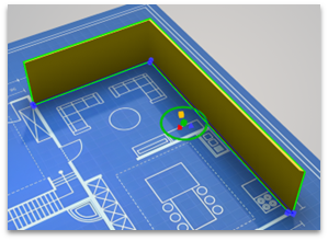
Then, by successive left clicks in the map, draw the contours. Once the shape is made, press right click to validate the path.
Undo the last point being drawn
During the drawing, to undo the last point placed, press the backspace key, then resume tracing.
Resume tracing an area after validating the tool.
To resume tracing a validated area, right-click when the mouse approaches one of the drawn sides.
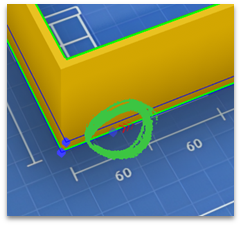
Vertex Management
Add a vertex
Left-click on a segment when the dot is added below the cursor.
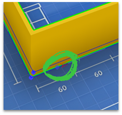
Removing a point
Right-clicking on a point deletes it.
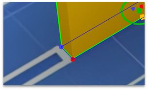
Move a point
Left-clicking on an already existing point allows you to move the current selection.
Create a structure from a shape
Pre-made shapes can be drawn automatically using the Create Structure tool.
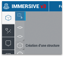
By default, the tool allows you to place a cube, but right-clicking on the icon allows you to choose a new shape to apply by default.
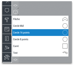
A left click will then place the element in the map.
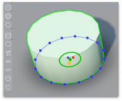
Add a shape
Start by selecting the shape you want to save.
In the menu on the right, click the Shape tab.
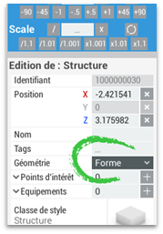
Then "Save shape":
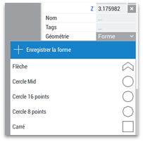
Give it a name to find it. :
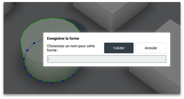
And validate.
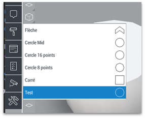
It now appears in the list.
Create an opening in a structure
The cutting tool accessible by the shortcut Ctrl + D allows you to draw an opening. A first click allows you to validate the cutting angle:.
Holding ctrl will draw a right angle.
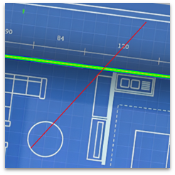
The second click allows you to validate the cut once the width has been defined by moving the mouse.
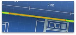
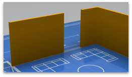
Align a vertex of one structure to another
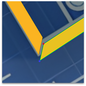
To precisely align a vertex to another vertex, you must activate Snapping, and choose the PolyVertex mode.
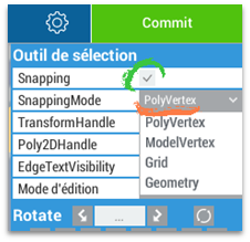
From now on, the pointer will be magnetized to nearby vertices and will allow them to be aligned.
Draw Right Angles and Parallel Lines
To draw perpendicular and parallel lines, you need to activate snapping.
Select the "Structure Drawing" tool. (The method is the same for zones).
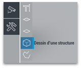
In the banner on the right of the interface, activate Snapping, and switch the snapping mode to "Geometry".
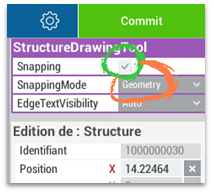
Once enabled, the mouse pointer will now be drawn to these angles while tracing.
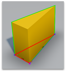
When 2 lines are colored red, it indicates what shape a right angle:
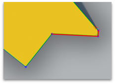
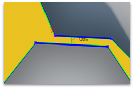
Coloured in blue, they indicate two parallel lines:
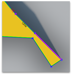
The dot will color purple when it is aligned with a line:
It is possible to temporarily enable/disable snapping, by holding the ctrl key.
Add a vertex on a straight line
The clipping tool accessible by the shortcut Ctrl + D allows you to draw an opening, but also to place a vertex on a line. This allows you to add a vertex while maintaining the linearity of the line.
To do this, you have to enter the shortcut and then cross a single line with the red line, and validated by a left click.
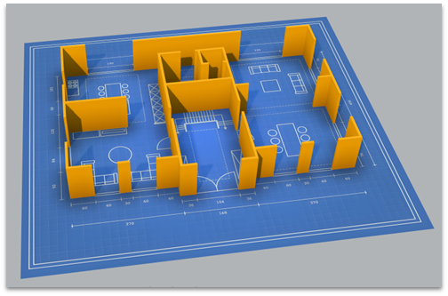
Areas
The zones are used to represent the floor, the floor of the different rooms.
Draw an area
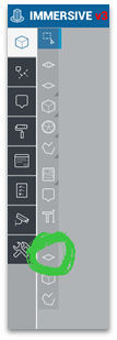
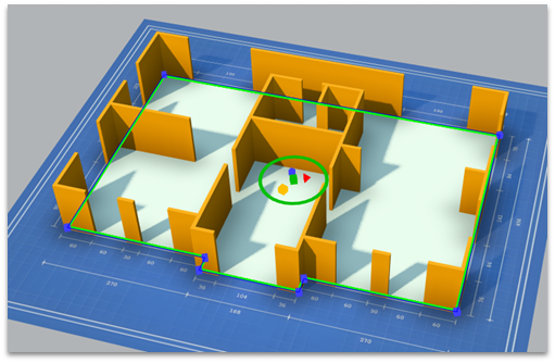
The method of creating zones is similar to that of structures. You have to use this tool and reproduce the tracing in the same way as for a structure. Left-click to add vertices, right-click to end the path.
Overlapping areas
It is possible to have several overlapping areas. For example, in the case of a temperature sensor dedicated to a room, or in the case of adding exteriors to differentiate different areas of grass, roads, etc.
To avoid any visual problems, you must tell the application which area is above, which area is below.
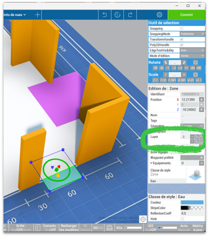
To change its position in the display order, you need to edit the Layer field in the right menu. The value indicating its position in the stack.
In the image above:
- The white area has a value of 0.
- The selected blue box has a value of -1.
- The pink area has a value of 1.